Basic Tutorial
|
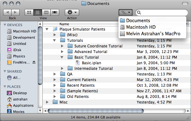
The tutorial file Basic.iplan can be found in the Tutorials folder which is located in the Plaque Simulator Patients folder which is in the Documents folder at the root level of your system hard drive. These files and folders were installed as part of your original installation or update of Plaque Simulator. Copies are also on your distribution CD and the latest versions are available via internet download from the Plaque Simulator website www.eyeplaque.com.
This tutorial outlines the steps required to create Basic.iplan.
|
|
|
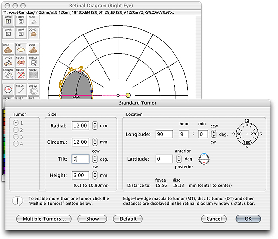
2. Select the Retinal Diagram window from the Window menu. In the central control group, use the Eye button to choose between left or right eye. Now click the Std. button. We will assume that funduscopic examination and ultrasound studies have measured a 6mm (as measured from the internal sclera) tall tumor with a 12mm diameter circular base located in the posterior hemisphere. The tumor is centered at about 10:15 (o'clock) on the diagram. Enter radial and circumferential dimensions of 12.0 mm for the tumor base and 6.0 mm as the apical height of tumor in the Standard Tumor Dialog. Click OK to exit the dialog.
|
|
|
Drag the tumor to the 10:15 location on the diagram. (You could also specify the coordinates in the Standard Tumor Dialog but dragging the tumor on the diagram is faster and more instructive.
|
|
|
4. Bring the Patient Setup window to the front by selecting it from the Window menu or clicking the mouse in the window. Click the Target button. This will rotate the eye for best viewing of the tumor.
|
|
|
When the Setup window is frontmost the Eye, View and Setup menus are added to the menu bar at the top of the screen. Select the Center plaque on menu from the Setup menu and choose Tumor 1 base.
|
|
|
Rotate the plaque as necessary using the plaque rotation control to orient the suture eyelets towards the front of the eye. The final setup should look like this.
|
|
|
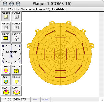
5. The next step is to load isotope into the plaque. In the Plaque window click the Isotope button.

|
|
|
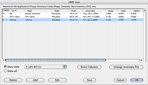
In the the Inventory dialog select model 6711 I-125 from the isotope menu and then click the Add button to create a new inventory item.
|

|
|
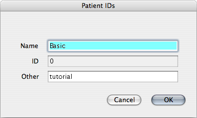
Name this new inventory item "tutorial", give it 13 sources of activity 4.14 mCi each on the current date. Click the OK button to close the Inventory index dialog.
|
|
|
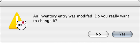
You will be alerted to confirm the change to the inventory file. Click the Yes button.
|
|
|
In the the Inventory dialog select the inventory you just created by clicking on it in the list. Click the OK button to return to the Plaque window.
|
|
|
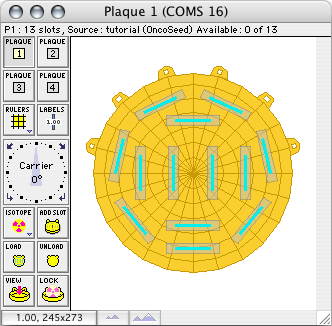
In the Plaque window click on the brown slot markers in the plaque to load slots individually or use the Load button to load all the slots at once. The sources you just created and selected will be loaded into the slots in the plaque carrier. The slot markers will change from brown to cyan blue to indicate an installed source.
|
|
|
In the Prescription window set the Prescribe to point to be the apex of tumor #1. Plaque Simulator sets the prescription point to the apex of tumor 1 by default when the program launches, and the recommended calculation mode settings are automatically set when you choose a plaque. You may override the recommendations if you wish using these buttons.
|
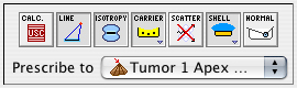
- Calc. - set to USC (the default).
- Line - set for linear sources (the default).
- Isotropy - set for anisotropic sources (the default).
- Carrier - enabled since this is a COMS plaque.
- Scatter - should be disabled since the Carrier factor already includes a scatter correction.
- Shell - when enabled, collimation due to the plaque shell is calculated.
- Slots - must be disabled (ie set to normal) since the carrier slots in a COMS plaque are made of silicone rather than gold.
|
|
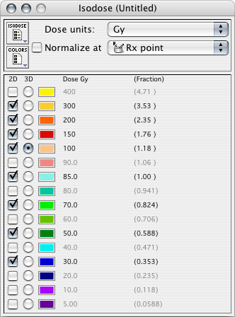
Click the Rx Units popup menu in the lower left corner and choose to display dose in Gy. Next, set the insertion date and time controls to the current date (ie the isotope calibration date) or something in the near future. You can adjust the removal date controls manually until the desired dose to the prescription point is achieved. In this example the Rx point is the tumor apex which is at a total distance of 6 mm (tumor height) + 1mm (scleral thickness) = 7.0 mm from the external sclera. Note that the orange highlighted row is the COMS 5 mm reference distance, NOT the Rx distance. The Rx point is hilited with a cyan background.
|

|
|
Alternately, you could click the removal time calculator button. In the Removal Time Calculator enter the desired dose (85.0 Gy), click the ∫ T button and then the OK button to accept the result.
|
|
|
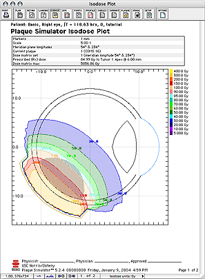
In the Isodose window select the 2D isodose contours and the 3D isodose surface to display using the checkboxes and radio buttons.
|
|
|
From the Dosimetry menu select Calculate 2D matrices.
|
|
|
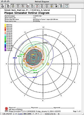
Dose on the meridian plane through the center of the plaque will be plotted in the Dosimetry window. Dose on the retinal surface will be plotted in the Retinal Diagram window.
|
|
|
|
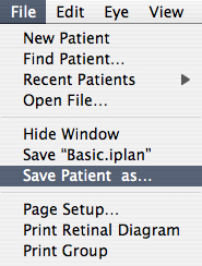
To save the treatment plan select Save Patient As... from the File menu.
|
|
|
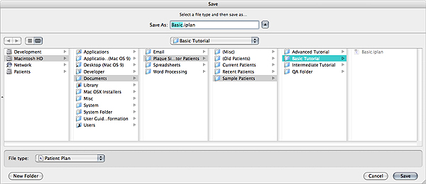
Use the MacOS navigation services to navigate to, or create a folder in which to save the treatment plan and click the Save button. The recommended location for patient plans is in the Plaque Simulator Patients folder which is in the root level Documents folder on your bootup (ie System) hard drive. This is where Plaque Simulator expects to find patient plans, but you are free to organize the files in other ways.
|
 |
|
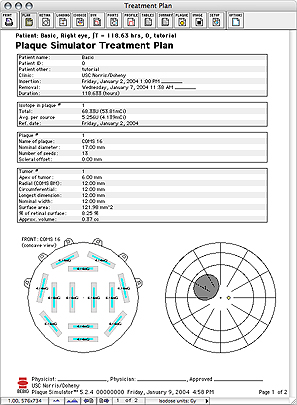
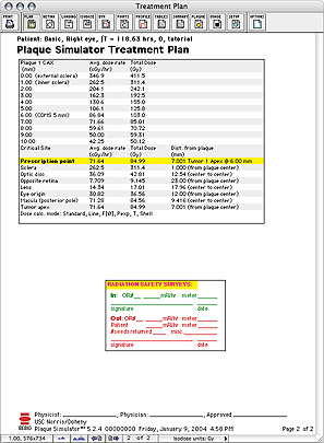
To preview the treatment plan documentation, open the Documents preview window (from the Window menu) and click the Plan button or select Treatment plan from the Documents menu. The treatment plan document consists of two pages. The page advance buttons along the bottom of the window select which page is being previewed.
|
|
|
|
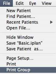
To print the treatment plan select Print group from the File menu. Before printing, be sure a printer has been selected in the MacOSX System Preferences or by using the Mac OSX Printer Setup Utility! After selecting a printer you should immediately select Page Setup... from the File menu.
|
|
Guide Contents