Creating a Model of a Specific COMS Plaque


Introduction

In this tutorial we will create a model of a specific COMS 10 mm plaque. Please note that generic models of all of the COMS, ROPES, and BEBIG plaques are selectable from menus in Plaque Simulator. End users of these commercially available plaques may never need to create specific plaque models. The COMS 10 mm plaque was selected for this introductory tutorial because it is a small, simple plaque with only 5 seed slots and therefore a logical choice for illustrating the process and editing tools.


Prepare pictures of the plaque face and carrier

With your flatbed scanner:

Begin by using a flatbed scanner (e.g. Epson Perfection Photo series with transparency option) to scan the face of your plaque shell at 1200dpi with a calibrating ruler nearby. Next, scan your Silastic carrier at 1200 dpi in backlit transparency mode. If you have several 10 mm carriers, you may wish to scan each of them to look for any variability. Eye Physics uses VueScan from Hamrick Software to capture our images.

Orient the plaque as symmetrically as possible with the suture eyelets towards the top of the picture. Orient the carrier so that the center seed is vertical. Include a translucent ruler with 1 mm increments along the top edge of the picture. A good file format to use is ".jpg". For best cosmetic results, use the Adobe Photoshop program to crop the scans and erase the background surrounding the plaque and carrier to pure white as illustrated on the right. Sample scans of most of the COMS plaques are included in the Plaque Simulator download.

COMS10mmShell1200dpi

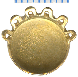
The COMS 10 mm shell scanned in 24-bit color flatbed mode at 1200 dpi.

COMS10mmCarrier1200dpi

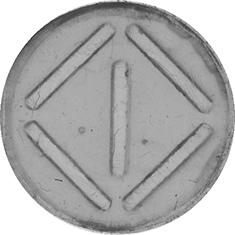
The COMS 10 mm carrier scanned in 8-bit monochrome transparency mode at 1200 dpi.


Find a similar plaque model as a starting point

From the Plaque menu:

Bring the Plaque window to the front by clicking in the window or by selecting it in the Window menu. Click the Plaque #1 button. From the Plaque menu, select a built-in model similar to the plaque you want to model.

PlaqueCOMS
COMSSilastic

Plaque Simulator includes predefined models of these COMS plaques with Silastic silicone seed carriers. The same models with gold insert seed carriers are also included.

COMSSilasticMenu10mm

Open the Shell Editor window

From the Plaque window:

PlaqueWndwWithCOMS10mm

From the Plaque menu:

  • Open the Shell Editor... window
PlaqueShellEditor
ShellEditor

The Shell Editor window.


Open the shell picture

In the Shell Editor window:

In the Picture controls group:

  • Click the Shell radio button.
  • Click the Open button.
  • Be sure Show is checked.
ShellEditorPictureControls
OpenCOMS10mmShellPicture

Navigate to find the picture of the shell face and open it.


Center the shell picture

In the Shell Editor window:

In the Picture controls group:

  • Translate shell picture to center
  • Rotate shell picture around center if necessary
  • Magnify shell picture if necessary so that 1 mm on the ruler matches 1 mm in the Shell Editor workspace. Rescaling the picture hould not be required if your scanner truly scans at 1200 dpi and saves that resolution in the file header. The purpose of the ruler in the scanned image is to confirm the calibration of the scanner and provide a way to rescale should it become necessary.

Before translating shell picture

ShellPictureOpened
ShellPictureTranslated

After translating shell picture


Open the carrier picture

In the Shell Editor window:

In the Picture controls group:

  • Click the Carrier radio button.
  • Click the Open button.
  • Be sure Show is checked.
CarrierPictureControls
OpenCOMS10mmCarrierPicture

Navigate to find the picture of the carrier and open it.


Center the carrier picture

In the Shell Editor window:

In the Picture controls group:

  • Translate carrier picture to center
  • Rotate carrier picture around center if necessary
  • Magnify carrier picture if necessary so that 1 mm on the ruler matches 1 mm in the Shell Editor workspace. The purpose of the ruler in the scanned image of the plaque face was to confirm the calibration of the scanner and provide a way to rescale should it become necessary. If your scanner is properly calibrated, you will not need a ruler in the scan of the carrier, just use the same scaling as for the plaque face.
  • Set the masking Inset to 0.6 mm. The nominal thickness of the lip of a COMS plaque is 0.5 mm. We are setting the inset mask to be 0.1 mm greater than the lip thickness to allow the picture of the carrier to rotate inside the shell just as the real carrier rotates within the real shell.
  • Enable masking by checking the Mask button. This clips the carrier image to a circle inset 0.6 mm from the exterior lip of the plaque.
  • Set the opacity of the carrier to 0.50. The carrier will now appear translucently within the lip of the shell.

Before translating carrier picture

CarrierPictureOpened
CarrierPictureTranslated

After translating and masking carrier picture


Set shell and carrier parameters

In the Shell Editor window:

  • Click the Params... button to open the Shell & Carrier Parameters dialog.
  • Since we began with a 'built-in' model of this plaque, we don't need to change any of these settings or properties, but now you know where to access the carrier property settings such as materials, thickness, color, ability to rotate and so on.
ShellAndCarrierParametersCOMS

These are the shell and carrier parameter settings for a COMS plaque.


Adjust the plaque perimeter

In the Shell Editor window:

  • Since we began with a 'built-in' model of this plaque, you don't need to change the plaque perimeter or properties, but because this is a tutorial, you should know how to.
  • To roughly edit the shape of the plaque perimeter, click and drag the perimeter defining nodes on the diagram.
  • To fine tune the properties at the plaque lip, select one of the perimeter defining nodes by clicking on it in the diagram or list.
  • Command-click to select multiple nodes. In this example nodes 0,2 and 4 have been selected. Node 0 should always be at 12 o'clock.
PerimeterNodeSelection
  • In the Perimeter controls group, click the Edit button to open the Lip Editor window. You can also access the lip editor by double-clicking a hilighted list item or diagram node handle.
LipEditor

Adjust the plaque eyelets

In the Eyelet Editor window:

  • Since we began with a 'built-in' model of this plaque, you don't need to change the eyelet properties, but because this is a tutorial, you should know how to.
  • Suture eyelets are attached to the perimeter defing nodes.
  • To add or delete an eyelet at one of the perimeter defining nodes, option-click on the node handle in the diagram.
  • Eyelet properties are set in the Eyelet Editor window which can be opened from the Eyelets... button in the Shell Editor window or from the Plaque menu.
EyeletEditor
EyeletSetup

To observe how parameters in the Eyelet Editor window affect the 3D model, set the Patient Setup window to plaque design mode and enable Track in setup in the Eyelet Editor window.


Open the Slot Editor window

In the Plaque window:

  • Install seeds in the slot placeholders.
  • In this example the central seed is still empty and marked with a 'heavy' brown placeholder line..
  • Set cursor mode to drag and rotate.
  • Drag the seeds over the wells in the silicone seed carrier.
  • Rotate to align with the slots.
  • Fine tune the coordinates and angles in the the Slot Editor window.

From the Plaque menu:

PlaqueWindow
PlaqueAppearanceHeavy

In the Slot Editor window:

SlotEditor
  • Fine tune the seed properties to overlay the wells in the silicone seed carrier.
SlotEditorSetup

To observe how parameters in the Slot Editor window affect the 3D model, set the Patient Setup window to plaque design mode and enable Track in setup in the Slot Editor window.


Save the plaque file

In the Plaque window:

  • Unload the seeds from the plaque.
EmptyPlaque

From the File menu:

FileSavePlaqueAs

Select Save Plaque As....

SavePlaque

Rename the new plaque and save it as an .iplq file in the Plaques folder in the Plaque Simulator Data master data folder. Update the Plaque Files menu.


Advanced Tutorial | Image window | Guide Contents