|
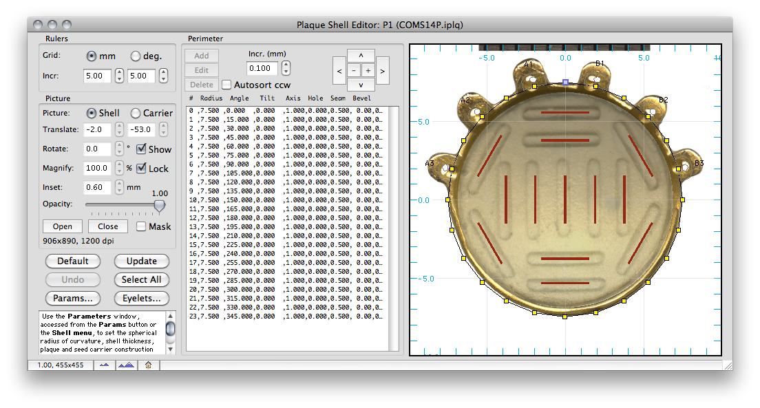
This dialog is used to interactively edit the shape of the plaque shell. An easy way to create a new shell is to load an existing shell and then modify it. After you have created the new plaque, be sure to save the plaque file. The plaque shell is described by up to 99 radial nodes. In this example of a COMS 10mm plaque there are 24 nodes represented by yellow boxes. Each node consists of a radial length and an angle. The length is the perpendicular radial distance to the central axis of the plaque. The angle is specified in degrees counter clockwise with respect to "12 o'clock". The nodes can be edited in the Control node list or interactively by simply dragging to a new position. Nodes can be selected by clicking, toggled by command-clicking, and ranges selected by shift-clicking. The central thickness of the plaque and the radius of the sphere to which it conforms are entered via the Params... button. You can attach a suture eyelet marker to any node by Option-clicking on the node. A picture of the plaque can be used as the background for this window. The picture can be rotated, translated and magnified as illustrated to match the model. Superimposing the shell model onto a picture of the plaque is very useful when modeling suture eyelets. IMPORTANT NOTE: The shell may not exceed a hemisphere. |