Revised to keep power wires behind airbag in pillar
With thanks to Martin Schmitt for pointers to avoid the airbag extension in the right pillar.
The objective of this do-it-yourself (DIY) project was to hardwire both a Blackvue 750s dashcam and a Uniden R3 radar detector in my 2018 BMW G30 540i sedan. This basic method should work equally well for any G30 vehicle but the pictures and descriptions are of course specific to my left drive (USA) vehicle. I intentionally chose to hardwire to a very convenient fuse panel so as to avoid any modification of the manufacturerer's wiring, and to a switched power source in that fuse panel that powers down a few minutes after the car is shut off and secured, rather than risk the devices remaining powered and accidentally draining the battery when the vehicle is not in use.
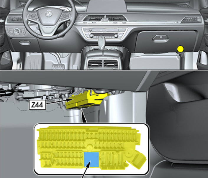
Some searching of G30 related material on the internet yielded all the necessary information required. The closest and most convenient power distribution panel to the front windshield area is Z44, located behind and to the right of the glove box.
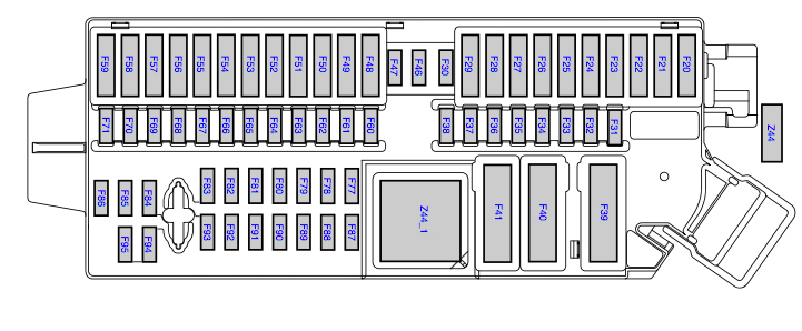
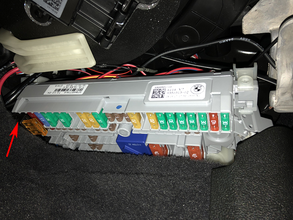
These are the fuses found in Z44.
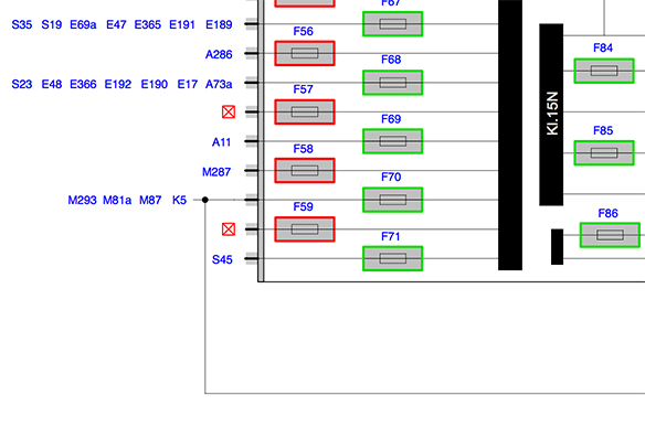
Studying the Z44 circuit diagrams revealed that fuse F59 is completely unused (indicated by a red box with an X) and is directly connected to the switched 12V power bus in the panel, so this is an ideal spot to install a fused expansion circuit using a STANDARD ATO size fuse tap (ie NOT a mini fuse tap) without disturbing anything else in the vehicle. If you need unswitched (continuous) power for dashcam parking mode operation, unused F28 is also available, but you risk running down the car battery if you don't drive the car very often.
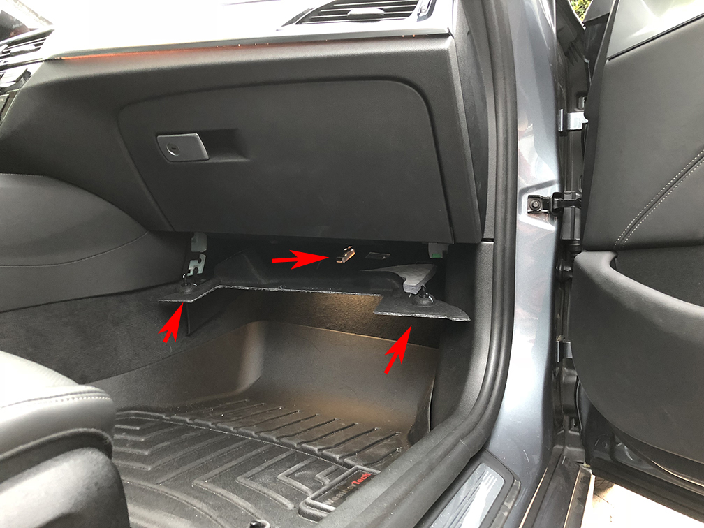
To access the Z44 fuse panel I simply removed the protective cover plate below the glovebox by rotating the two retaining clips 90 degrees. Then I unplugged the power wire connector from the LED light socket mounted in the cover. I then removed the cover and set it aside in the trunk for safe keeping.
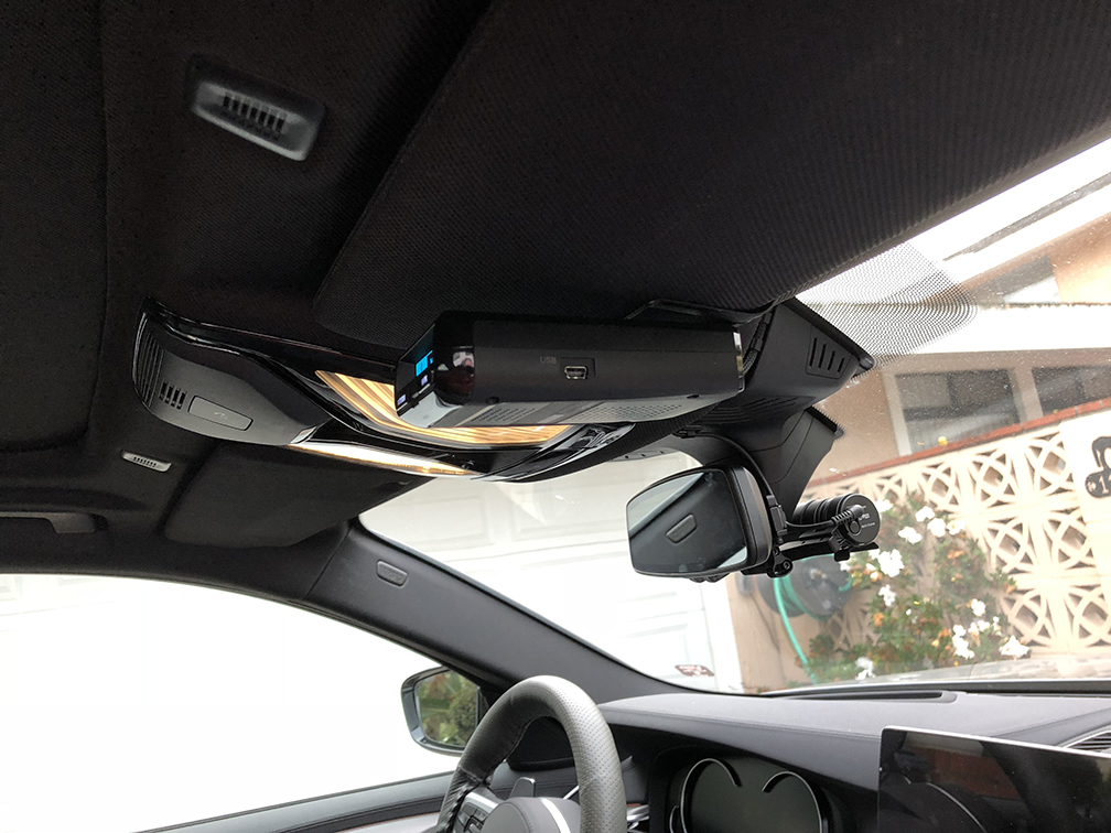
I chose to mount my dashcam using the Blendmount mirror mount designed for my car and the Blackvue 750, and I mounted my radar detector on the passenger side visor clip where it is stealthy and out of the sun. I used a tiny file to slighly widen the locking slot in a Radenso visor clip (I widened the slot in the direction of the end of the tongue) where it slides into the radar detector because there was no specific clip available for the R3 model.
I purchased hardwire kits for both devices online, one from Blackvue for their dashcam, and for the Uniden R3, a kit from Radar Mount, the model RJ11 Direct Wire Radar Detector Hardwire Power Cord for Uniden (3005001U). These were readily available on Amazon and eBay. Each hardwire kit contains the appropriate power connector for the respective device attached to a long power cord.
I tested the two devices initially using the "cigarette lighter" power cords that came with the devices to assure that they were working properly. The radar detector immediately detected a GPS signal so the visor location is fine. Then, using the hardwire kits, and starting from the devices, I routed the hardwire power cords up into the headliner where it meets the rearview mirror and then across to the right side pillar. No tools were required to do this. I used some tiny mounting clips that came with the dashcam to keep the wiring neat.
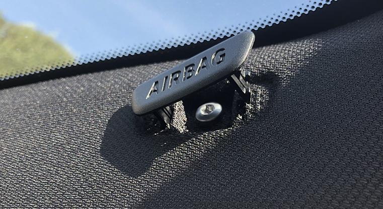
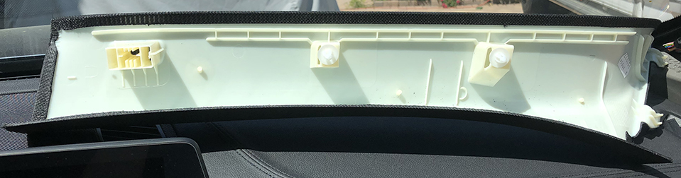
I used a plastic pry tool to remove this little cover plate labeled "airbag" to access the screw that holds the pillar cover in place. Use a T20 to remove the screw.
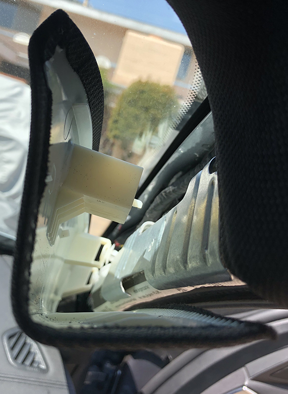
Then gently, but firmly, pry off the pillar cover, its held by that screw thats now removed and 2 white plastic expansion rivets that will pop out.
Set cover aside.
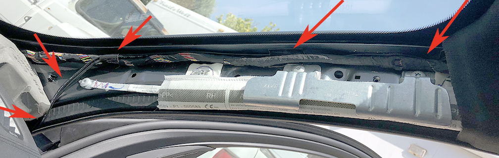
Route the power wires behind airbag, I used electrical tape to bundle them along with existing wire bundle.
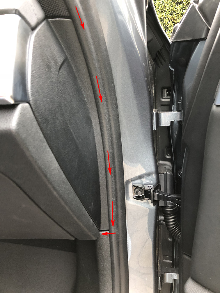
and then route under the molding and down to the base of the glove box, and then across into the space where Z44 is located. Return the right pillar cover to its original position carefully to avoid damaging the white plastic rivets when you pop them back into the frame, and return the screw and airbag label.
I trimmed the power cords to the length needed to reach F59. This meant removing all the now extraneous fuses supplied with the hardwire kits because I will instead be using a dedicated fuse tap in F59. The RJ11 cord was wired with 4 conductor "telephone" type wiring. The green and yellow wires are not used in this application so they can both be trimmed away at any convenient location. The red and black wires from the RJ11 cord are the 12V and ground lines. I used a wire stripper to remove a half inch of insulation from the RJ11 cord red wire, the dashcam cord red wire, and the fuse tap red wire. I twisted all the bared ends of the red wires together and then soldered the whole bundle. Before soldering I positioned a length of 1/8 inch heat shrink tubing over the wire bundle (far enough from the solder joint that it wouldn't shrink prematurely) and after soldering slid it over the solder joint and shrank it. You could also use crimping devices to make this bundle connection but I happen to be comfortable with soldering owing to a strong background in electronics, including radio and computer hobbies.
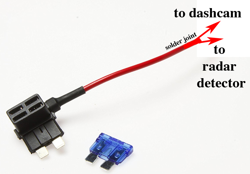
I did the same with the black (ground) lines connecting them to a 1 foot length of black wire trimmed from the RJ11 kit that had a grounding lug already provided. I elected to install an orange 5 amp fuse in the upper bay of the fuse tap instead of the blue 15 amp fuse that happend to be included with the fuse tap, and I kept the lower fuse tap bay empty because F59 was empty to begin with in the Z44 panel. Orientation of the fuse tap is important to assure the fuse provides protection as expected. This is the correct orientation for the fuse tap. I used (Amazon Standard ATO Fuse Tap 16awg with 15A Fuse - 5 Pack) .
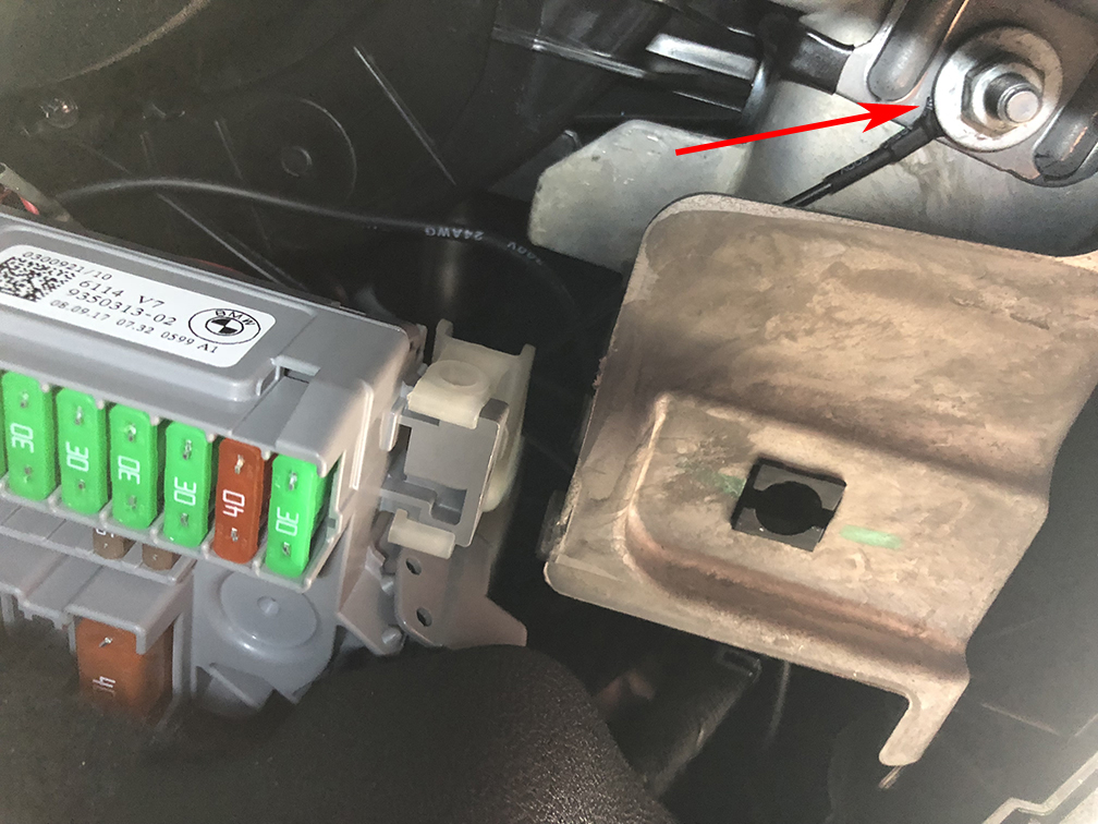
Under the glovebox near the F20 end of panel Z44 is a convenient nut that provides a grounding point. I used a socket wrench to temporarily remove the nut, slide the hardwire grounding lug over the bolt, and then replaced the nut. Everything powered up and works. I completed the project by reinstalling the cover panel (and don't forget its light connector) under the glove box.