Points of Interest

Points of Interest are best created interactively using POI cursor mode in either the Planar Dosimetry and/or the Retinal Diagram window. Note: the example equatorial POI on the right appears on both the retina and a meridian plane.

  • Select POI cursor mode in either window. POICursorMode
  • Navigate the meridian or coronal plane to pass through the desired point and then click on that point.
  • For locations on the retina simply click on the diagram.
  • Sequential clicks digitize additional POI up to 16 total.
  • Existing POI can be dragged to new locations.
  • Double clicking on an existing POI opens a dialog sheet in which you can edit its properties. In this case the auto size property has been disabled and the POI marker and font size were been manually scaled using the quick-set convenience slider to a 2.5 pixels marker radius and 20 point font respectively. The font and marker properties of a POI apply to all 2D displays, so the same font and marker size are used in both the planar dosimetry and retinal diagram windows. A POI's 3D properties, and a greater range of 2D options, can be customized in the POI style sheet.
POIDigitize
POIDigitizeSheet
POIDigitizeRD
POIDigitizeRDSheet

Points of Interest Window

From either the Diagram menu:

PointsOfInterest

or the Plot menu:

PointsOfInterest

The Points of Interest (POI) window summarizes the properties of all digitized points of interest. PS supports up to 16 POI. The radio buttons along the left side select the currently active point. The active point is the one which will next be created or changed when digitizing points in either the Planar Dosimetry or Retinal Diagram window.

You can edit the coordinates, color, label, choose to use the point for dose prescription (Rx) or normalization, as the target of source percentage contribution calculations, whether to draw the point in the Dosimetry, Retinal or Setup windows, and elect to apply a custom text style to the point.

POI are initialized at (-100,-100,-100) to signify that they are invalid for dose and other calculations. Digitizing a point will automatically mark it as included, but you can manually "uninclude" it if you wish. Clicking the include checkbox of an invalid point will reset its coordinates to the eye center (0,0,0) as a convenience.

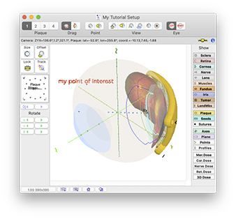
The Set Style button opens the text style dialog sheet from which you can customize the label (and point marker) appearance. In the example below and on the right, the font size used for 3D labeling has been enlarged to 72 point.

POIDigitize3D
POIWindow
POITextStyle