Eye Size Window

In this window one can manually adjust Plaque Simulator's model of the eye more precisely than can be achieved using the graphical Eye tool in the Image window.

SizeBtn

From the Setup window click the Size button to open the Eye Size window.

Eye size

  • The controls in the toolbar group simplify the creation of standardized models of various diameters and shapes of eyes. These models are used, for example, to design Eye Physics 3rd generation slotted plaque prototypes.
  • To create a model of the 24 mm diameter COMS standard eye click the COMS Standard button.
  • To create a model with the same relative proportions as the COMS standard eye, enter the equatorial diameter (D) and click the Standard Proportions button.
  • EyeBtnFor patient specific planning, it is recommended that, at minimum, an axial MPR image (CT or MR) be created and loaded into the Image window. After calibrating the axial image, use the interactive Eye tool to adjust the eye model interactively to match the actual patient eye. Sample CT images are provided with the program.
  • You may optionally overlay either an axial, sagittal or T-Mer. MPR image in the Eye Size window and rotate the model to match the orientation of the Eye tool in the Image window. Note: the axial image is the recommended overlay here because the optic nerve does not intersect a sagittal bisecting image and may not be visible in a T-Mer. image unless the tumor happens to lie near the axial plane.
  • If the eye no longer has a lens you can disable the display of all lens modeling and dosimetry in the Lens control group.
  • StepperIncrMenu Stepper increments of 1.0, 0.1, 0.01, 0.001 or 0.0001 (mm or degrees) can be set using the stepper increment menus.

AxialOverlay
  • Arranging the Eye Size and Image windows side by side as illustrated on the right allows you to simultaneously fit the eye model to the patient interactively and quantitatively.

AxialImage

The Image window Eye tool provides an interactive graphical means of adjusting the eye model to fit MPR (e.g. CT and MRI) imaging. Simply drag the model's control handles to adjust the eye dimensions.

TMerOverlay
  • On the tumor-meridian (T-Mer.) image of the Image window, if you enable the tumor tool, you can drag the tumor base (dark brown) control handle of the tool along the inner scleral surface to mark the approximate location of the tumor as it appears in the T-Mer. image. The location of the tumor base appears in the Eye Size window as the T-Mer. tumor angle (e.g. -68.37°) which is the angle in the meridian plane between vectors originating at the eye origin and pointing towards the tumor base and the posterior pole. This angle is only used to help PS decide how to best rotate the meridian dosimetry plane about the AP axis to overlay the T-Mer. image when auto-centering the plane. The tool does not reposition the tumor base.

TMerImage

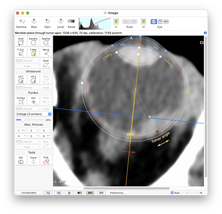
Note: the beige colored apex control handle of the Image window tumor tool does change the tumor height, but it is limited to the vector pointing from the tumor base towards the eye origin. If the tumor is not symmetric about this vector, set the tumor apex from the Retinal Diagram window.