When an image has been loaded into an Image window buffer, the button for that buffer will display a small, dark gray badge to the upper right of the button icon.
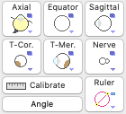
- To calibrate a CT (or MR) multiplanar reconstruction (MPR) image you must first activate one of the MPR group images (axial, equator, sagittal, t-coronal or t-meridian) then enable and position the MPR ruler in the Image window.
- Click the Ruler button in the MPR image controls group (its just above the button labeled Angle) to display Plaque Simulator's MPR calibration ruler. Although PS optionally supports up to 4 rulers per image, only the primary ruler (#1) may be used to calibrate an image.
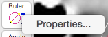
- Ruler options are enabled and accessed from the Properties... item of the ruler button's contextual menu. Optional rulers #2 through 4 share the image calibration established by ruler #1.
- Ruler properties that you can customize include:
- A label for the ruler
- Color
- Line width
- Font size
- End marks
- Line style
- Label angle
- Label position
- Showing the outer circle
- Showing the ruler
- In the Image window, drag Plaque Simulator's MPR primary ruler (#1) over the calibration indicator of the image or any object in the image of known dimensions, typically about 40 or 50 mm.
- Adjust the diameter of Plaque Simulator's MPR ruler by dragging the control boxes until the outer circle diameter fits the known object. The control boxes change from the ruler color property to yellow when the boxes are horizontally or vertically aligned. In the example on the right, the diameter of Plaque Simulator's MPR ruler represents 50 mm according to the green colored calibration indicator in the image.
- With the MPR ruler still enabled, click the Calibrate button in the CT Image controls group to open the calibration dialog sheet.
- Enter the diameter in mm (e.g. 50 mm). Buttons for 30, 40 and 50 mm diameter presets are also provided as a convenience.
- You can propagate this calibration to other images by selecting any or all of the other MPR images that you know will use the same calibration.
- Click the OK button to exit the sheet.