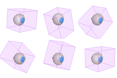
Isodose surface calculations can add significantly to dose calculation and 3D rendering time. Since isodose surfaces are not necessary for routine treatment planning, the 3D matrix is not created automatically. Before calculating isodose surfaces you must allocate memory for the 3D Matrix by selecting Allocate 3D matrix from the Dosimetry menu.

If a 3D matrix exists, it can be used to accelerate 2D surface calculations. This may be useful for plaques with large numbers of sources and constant source distributions such as the BEBIG Ru-106 plaques which are modeled as hundreds of patch sources. Since the matrix is normalized, the dose distribution can be "precalculated" once. IMPORTANT: if the radionuclide distribution on a plaque, or the calculation mode (isotropic, point source, etc...) settings are ever changed, the matrix would no longer be valid and must be recalculated. It is advisable to lock plaques when doing 3D calculations.


3DMatrixMovie

Matrix bounds

The 3D matrix bounds are 20 mm lateral to the plaque's central axis (CAX), 5 mm behind the plaque, and 40 mm in front of the plaque. Dose outside these bounds is assumed to be zero. The 3D matrix has nonuniform density. The spacing between calculation points varies between 0.5 and 1.0 mm laterally and between 0.25 and 2.0 mm in front of (and behind) the plaque with the greatest calculation point density at the plaque face. The matrix data are normalized to a point 2.5 mm in front of the plaque on the CAX. When the matrix is used for isodose calculations, only dose to the normalization point needs to be recalculated to adjust to changes of implant date and/or duration.
3DSurfaceMovie

Isodose surface

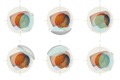
The 3D matrix is referenced to the coordinate system of the "active" plaque. Illustrated to the left are the matrix bounds and the 85 Gy isodose surface of a BEBIG CCB plaque.


Guide Contents